Retrofitting a MK7 Multi Function Steering Wheel in a MK4
This guide will show you how to retrofit a Multi Function Steering Wheel (MFSW) from a MK7 in your MK4 Golf/Bora/Jetta. This guide is a work in progress
Introduction
Working principle
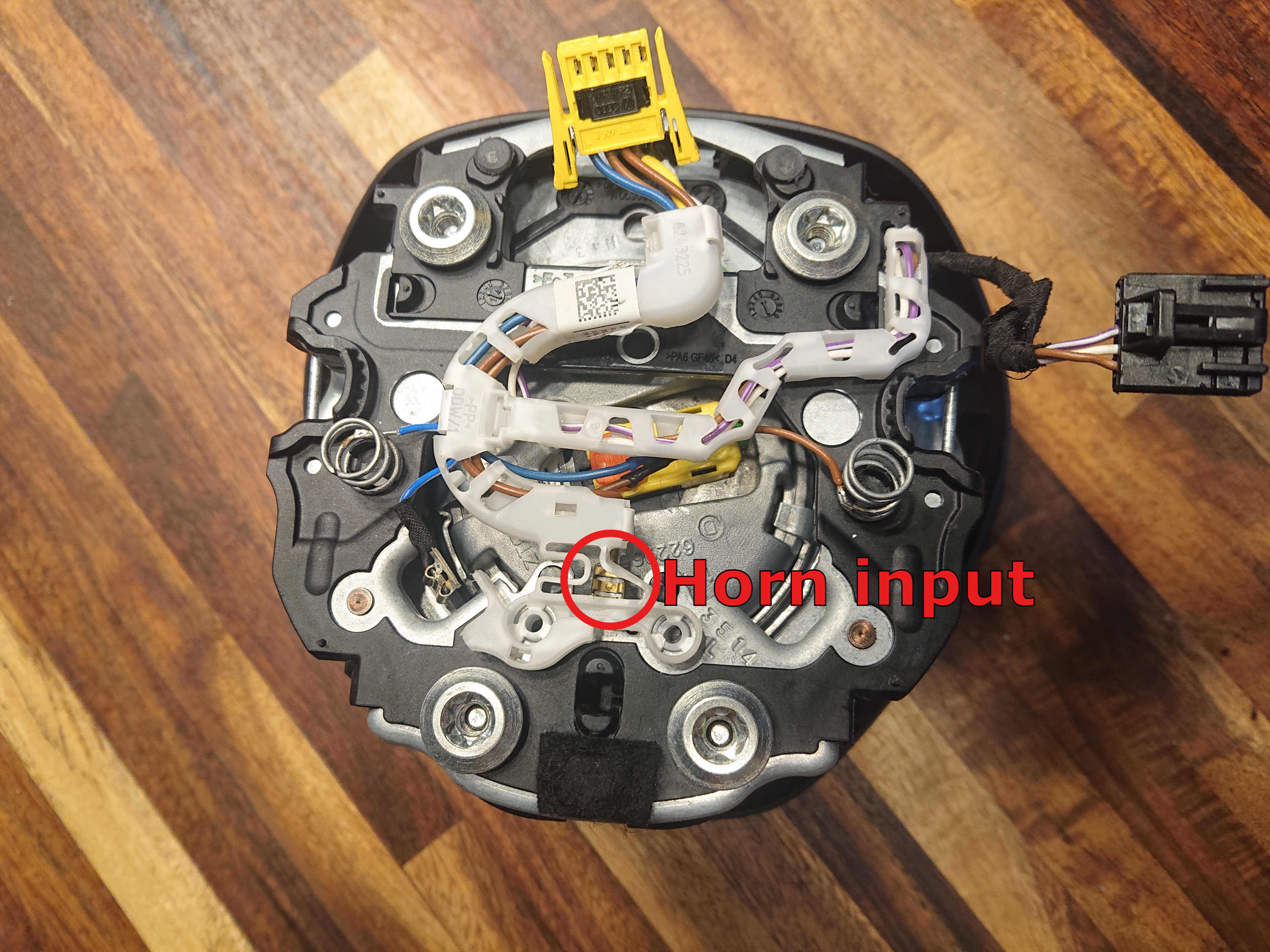
The main issue when trying to fit a MK7 MFSW in a MK4 is the lack of pins on the steering wheel's clock spring and the unknown communication protocol. The MK4 clock spring has 5 pins 4 of which are used for: Airbag input, Airbag Ground, Horn input, Horn ground. This leaves one pin remaining.
To get another free pin we will take the horn ground and connect it to a grounded metal part of the steering wheel and use that as ground. This gives us two pins, one will be used to power the buttons, the other for communication, ground for the buttons will also be taken from a grounded part of the steering wheel.
A micro controller (Arduino nano) will be placed in the dashboard, it will send the status of the dashboard lights through the communication wire and a microcontroller placed on a custom PCB in the steering wheel (Original PCB's will be replaced) will reply with the status of the buttons.
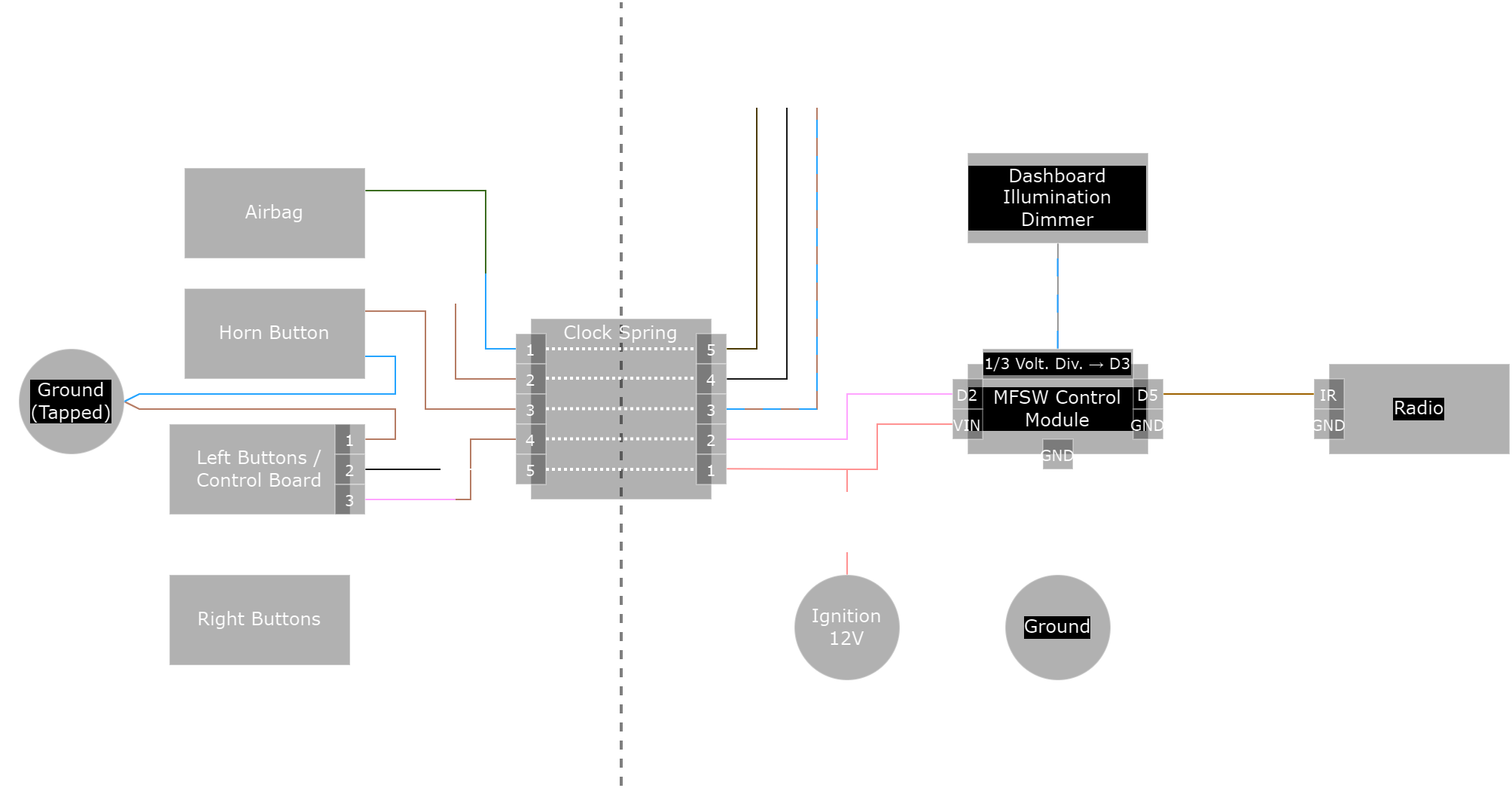
Electronics Overview
Required parts
- MK7 MFSW
- MK7 MFSW Wiring Harness (In steering wheel)
- Original MK4 Steering wheel wiring harness
- Donor MK4 Steering wheel wiring harness (ie. 1J0 971 584 H)
- Custom steering wheel PCBs + Components (See PCB Ordering + Assembly)
- Custom MFSW control module PCB + components (See MFSW control module)
- Arduino Nano or similar for flashing firmware onto steering wheel and MFSW control module
- Wiring
- Wire harnessing tape
Required tools
- 12mm XZN Bit
- Wire Cutter
- Wire Stripper
- Soldering iron + supplies
- Mini USB Cable
- 6 Female to Female Dupont Wires (To connect the Arduino to the modules for flashing firmware)
- Plastic trim removal tools
MK7 wheel preperation
PCB Ordering + Assembly
You can order the PCBs to be produced at companies like JLC PCB.
The files include component placements which can be used to have part of the components soldered using the PCB Assembly (PCBA) service of JLCBPCB. I recommend you to atleast let the components on the bottom layer of the left PCB be soldered using this service due to the difficulty of soldering these by hand (Deselect J1, J2 and ICSP as JLC does not have the right components for these).
The files for the PCBs can downloaded here:
Left Board
Right Board
The following parts remain to be ordered and soldered seperately:
- 2x 2x6 2.54mm SMD Male Header
- 1x 1x5 2.54mm SMD Right Angle Male Header
- 1x 12 Wire 1.27mm pitch Ribbon Cable
- 2x 2x6 2.54mm Connector for 1.27mm pitch Ribbon Cable
Flashing Firmware
The firmware can be loaded onto the left PCB by using an Arduino as ISP. The steps below assume you are using an Arduino Nano, for other boards slightly different steps might be required.
- Install and open the Arduino IDE on your computer.
- Goto File → Examples → 11.ArduinoISP → ArduinoISP
- Connect the Arduino you will use to flash the firmware
- Select Tools → Boards → Arduino Nano
- Select the COM Port for your arduino under Tools → Port
- Click Upload and wait for it to complete
- Connect the ISP pins from the Arduino to the left PCB like shown in the table below.
- Open the MFSW_Wheel sketch from MFSW_Firmware.zip
- Select Tools → Programmer → Arduino as ISP
- Upload using Sketch → Upload Using Programmer
ICSP Connections
| Programmer Arduino Pin | Left PCB ICSP Pin |
|---|---|
| Pin 10 | RST |
| Pin 11 | MOSI |
| Pin 12 | MISO |
| Pin 13 | SCK |
| 5V | 5V |
| GND | GND |
Wiring
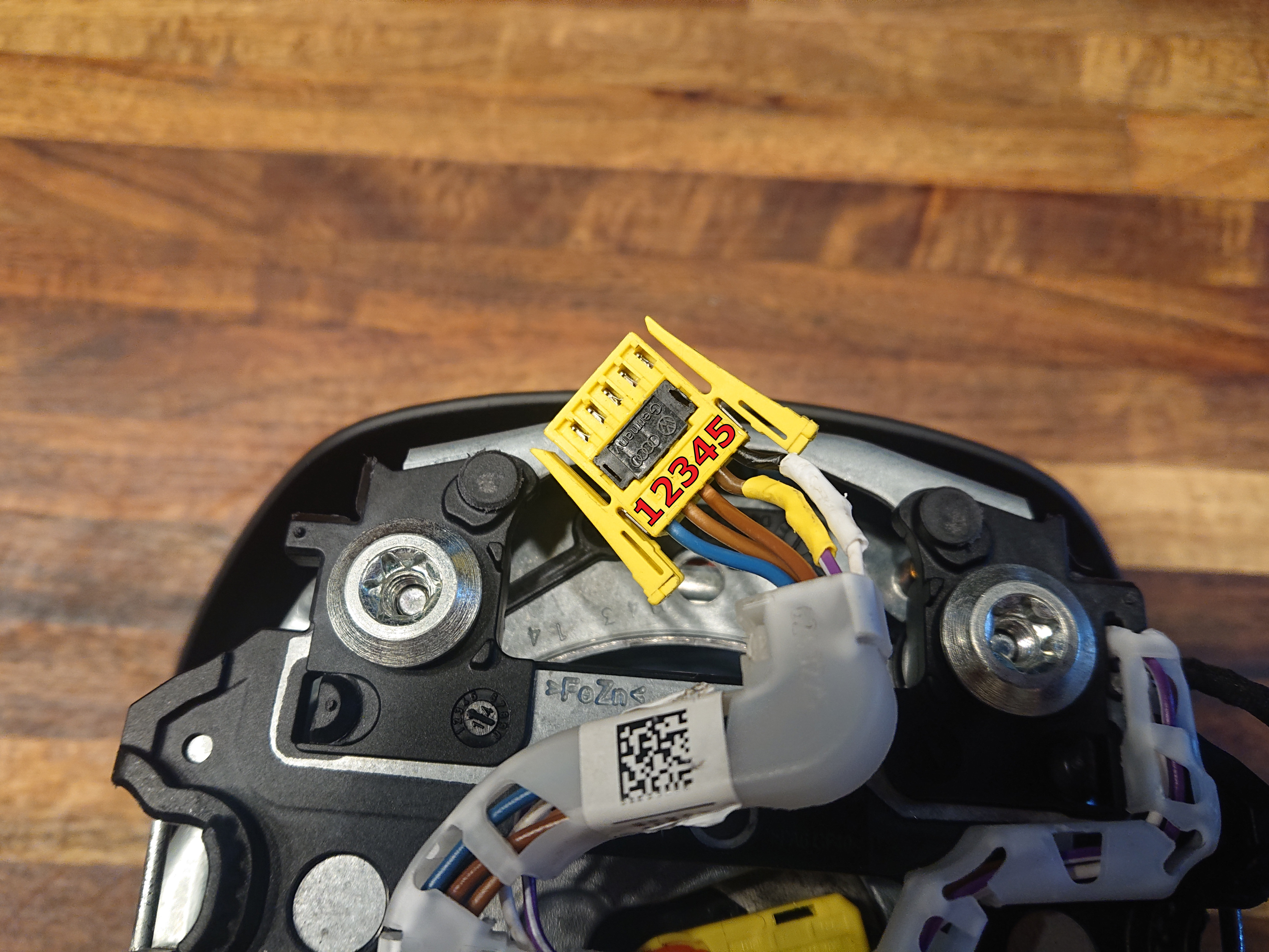
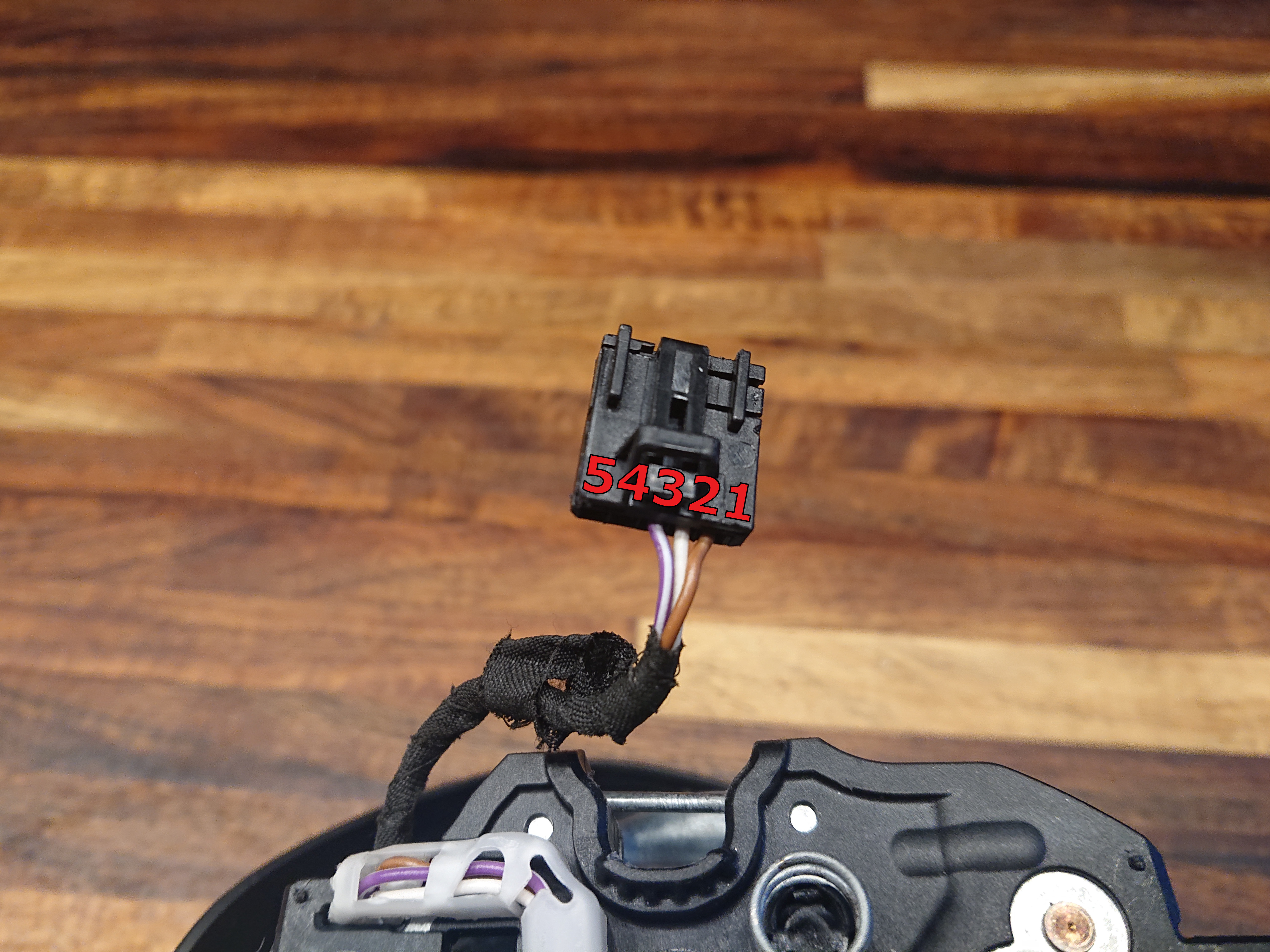
To make the wiring harness for in the steering wheel you will need to attach the clockspring plug from the MK4 to the wiring of the MK7 as told in the table below, the colors are only for reference to the images (these also show the pin numbers), some of your wires might have different colors.
You will need to put one additional wire in the MK4 plug from a donor MK4 harness since it normally only has 4 wires and you need 5. To remove a wire from the donor harness pull out the pink/black (Black in my case) retainer, then carefully press the small metal tab on the side of the contact to be able to remove it. To insert the wire in the other plug lift up the retainer and slide it in in the same orientation as you took it out.
| MK4 Side | MK7 Side | Description | Image |
|---|---|---|---|
| Pin 1 (Blue) | Airbag Green | Airbag | 1 & 2 |
| Pin 2 (Brown) | Airbag Black | Airbag | 1 & 2 |
| Pin 3 (Brown) | Spade terminal | Horn Input | 1 & 4 |
| Pin 4 (Brown) | MFSW Pin 3 | MFSW Signal | 1 & 3 |
| Pin 5 (Black) | MFSW Pin 2 | MFSW 12V | 1 & 3 |
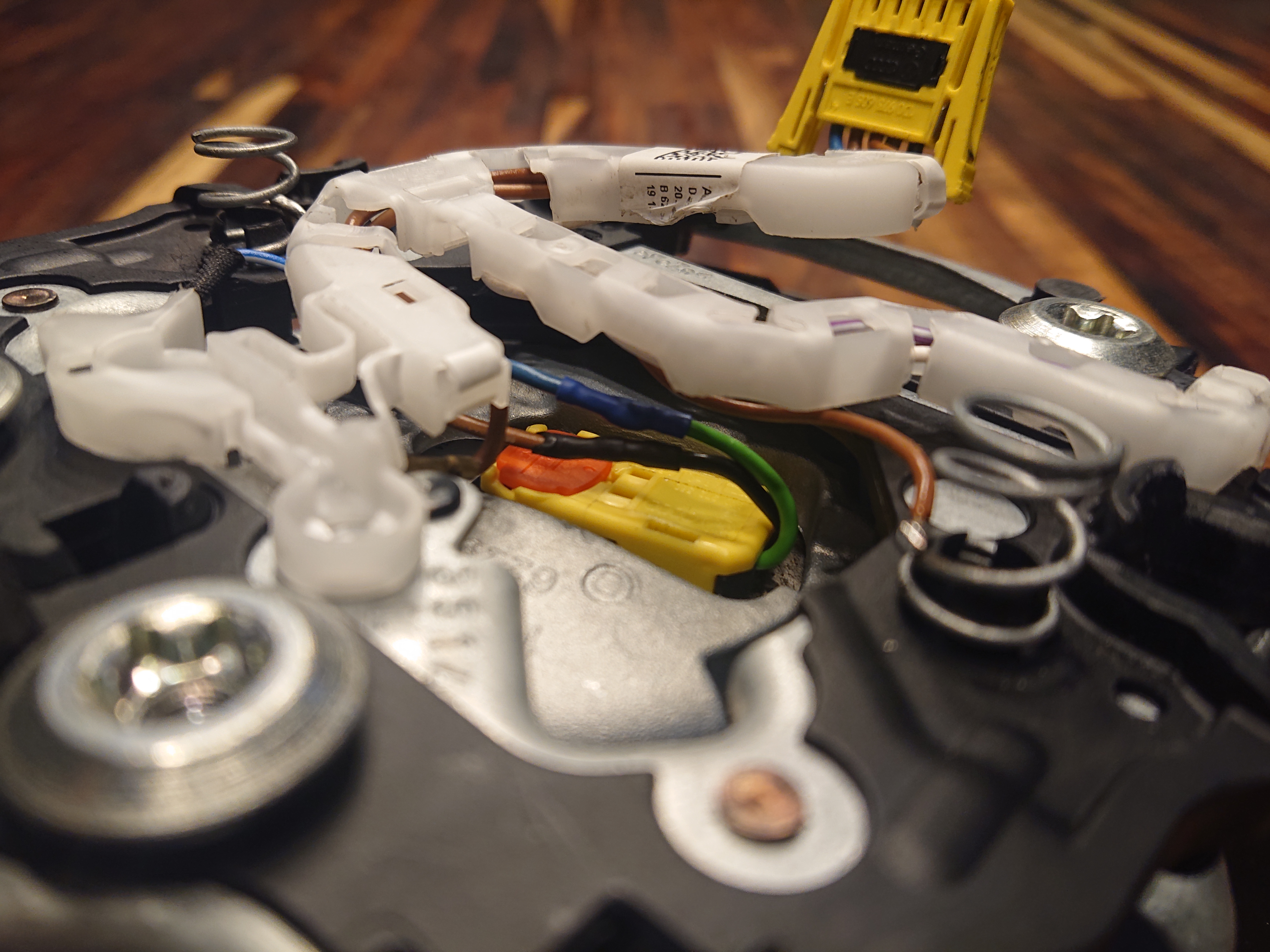
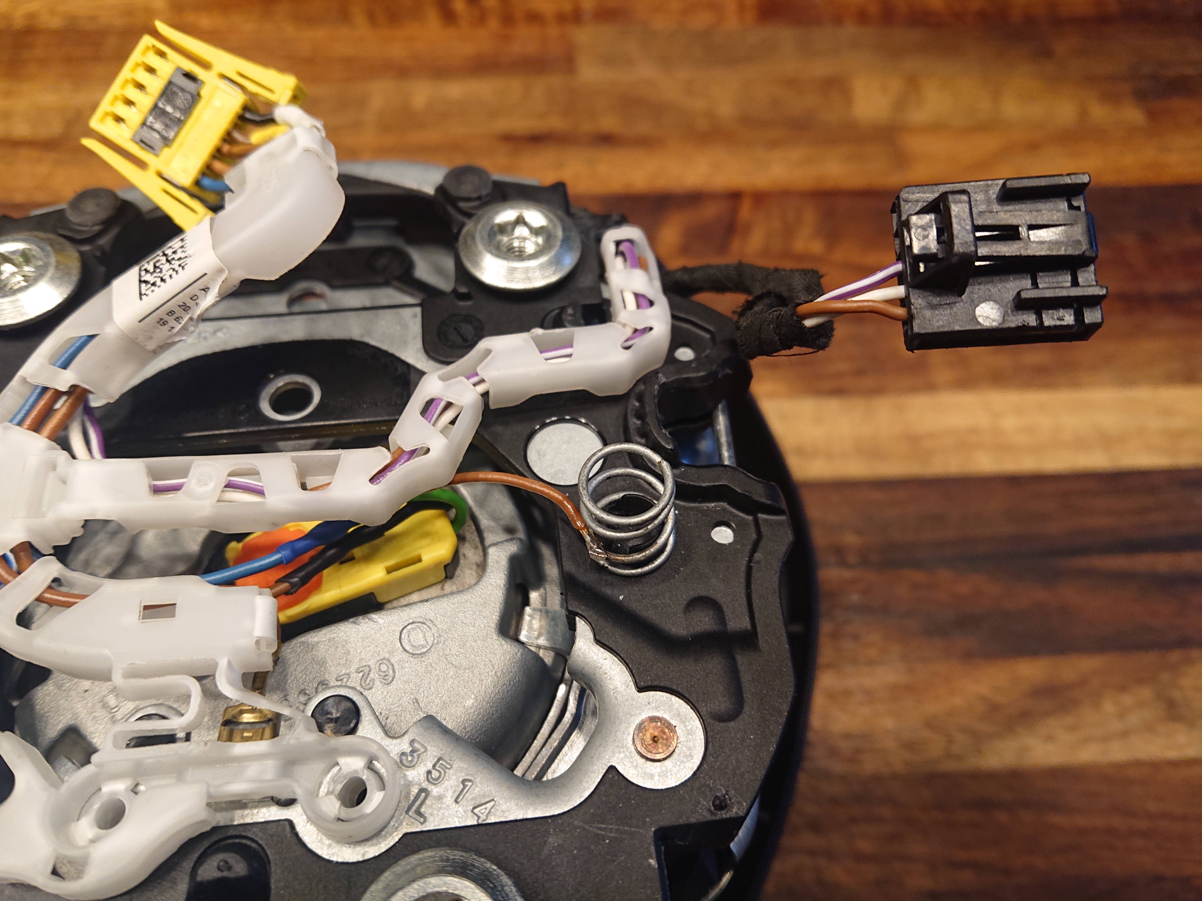
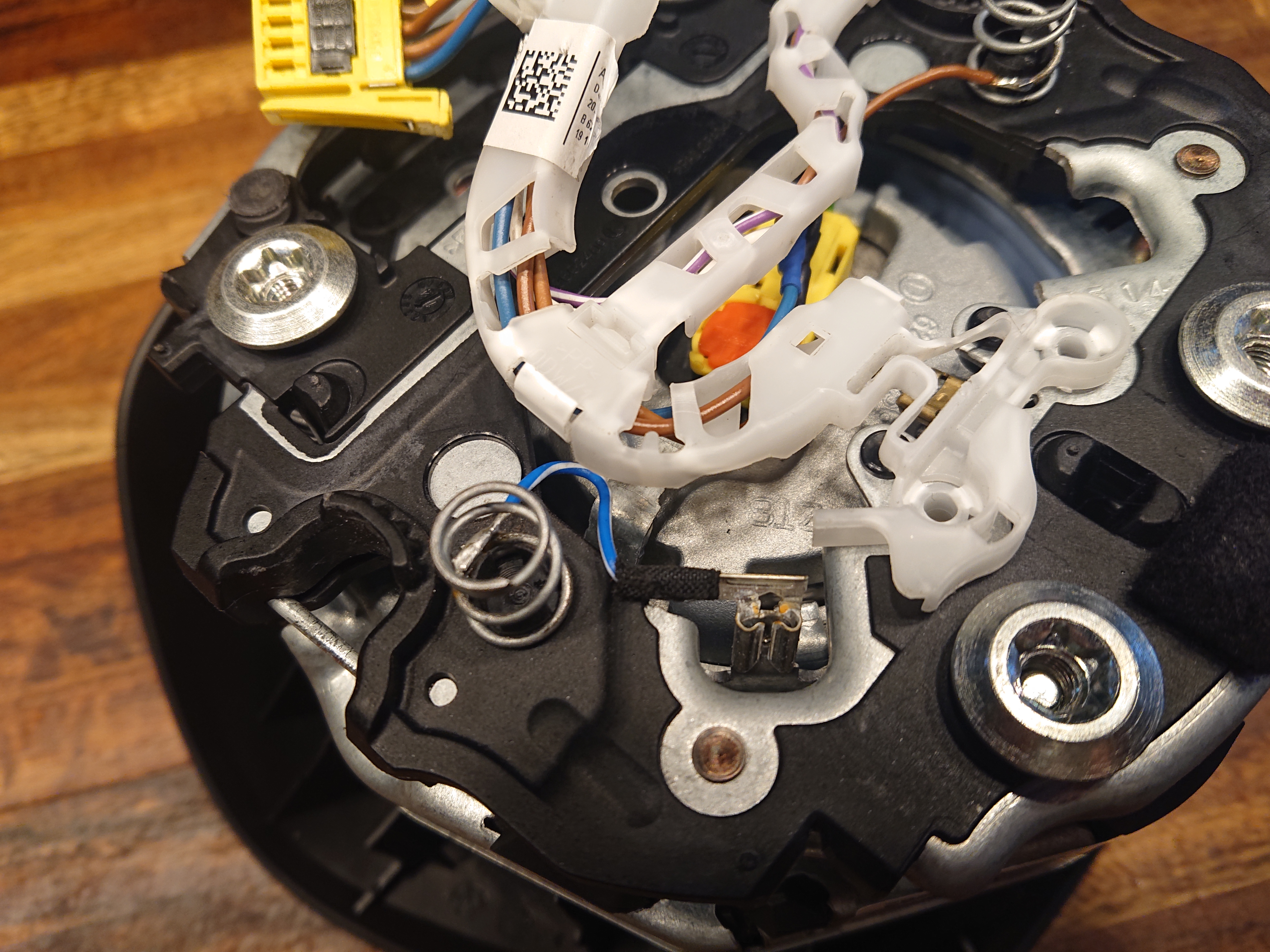
Additionally drill and tap a grounding point into the steering wheel, and use it to ground pin 1 from the MFSW plug (Brown), and the horn ground (Blue/White). The images (5 and 6) still depict an old method I used by attempting to use the springs on the back of the airbag as ground, but this would fail over time.
Click on the images to show them in full size.
 1
1
 2
2
 3
3
 4
4
 5
5
 6
6
Assembly
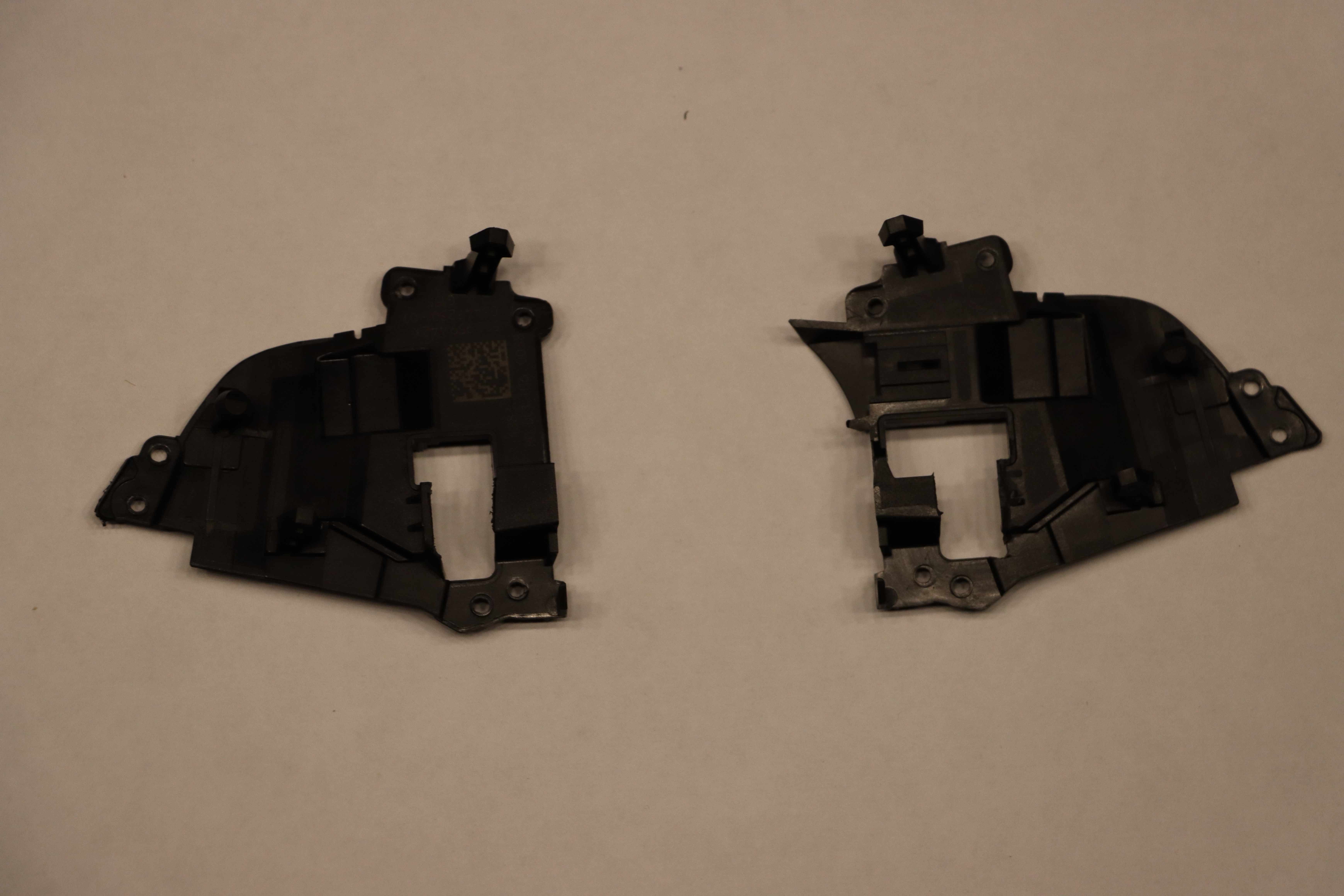
Remove the trim containing the buttons from the steering wheel. I find it easiest to start by prying it up a bit at the bottom and then work my way to the top. Dont bend the trim too much or it will break, also be carefull with the leather next to the buttons, it might be caught on the edge of the trim.
Remove the 6 torx screws marked in the image below and take out the button assemblies. Then remove the remaining 8 screws to open them up, I used a flathead screwdriver for this.
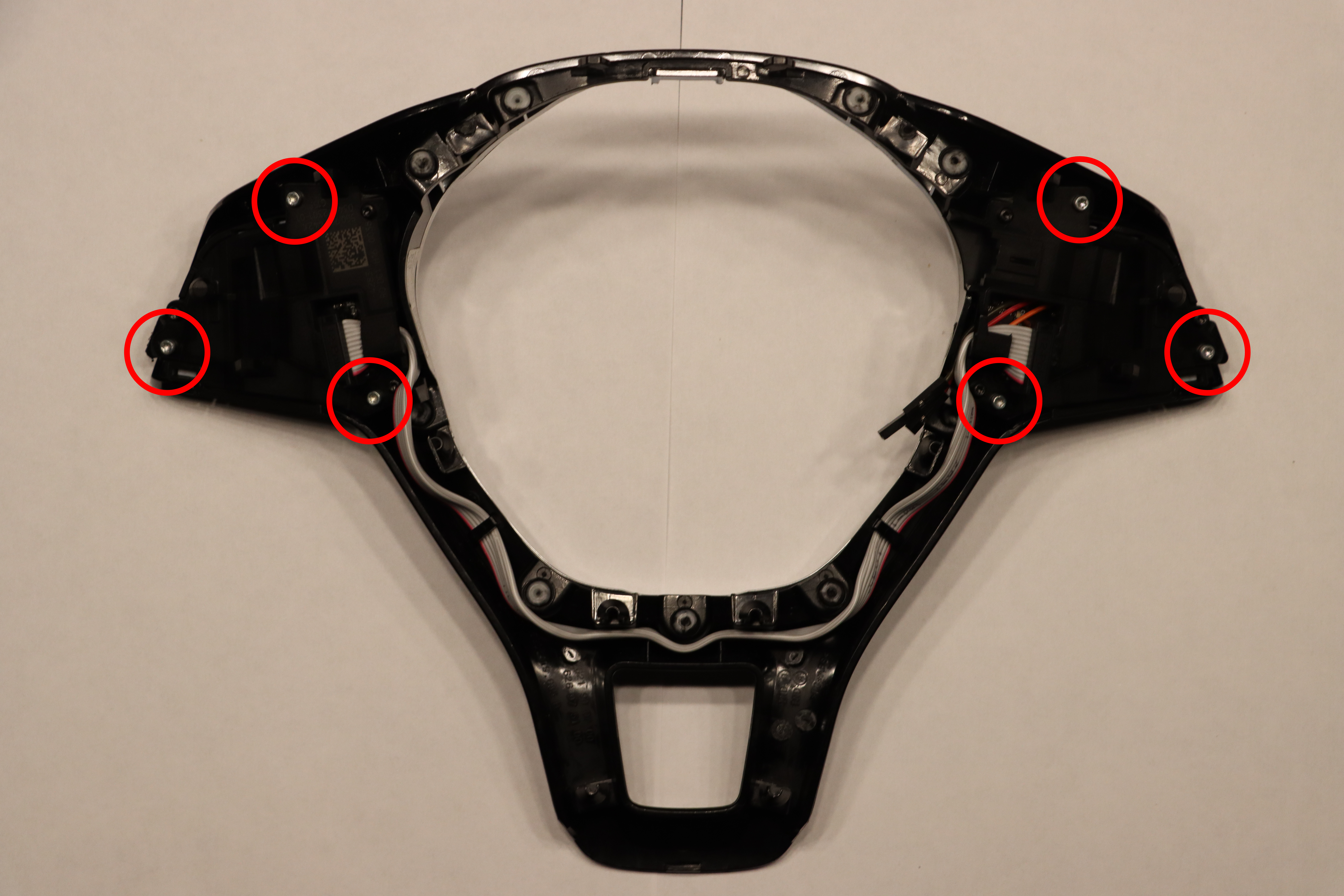 Screws that hold the buttons in place.
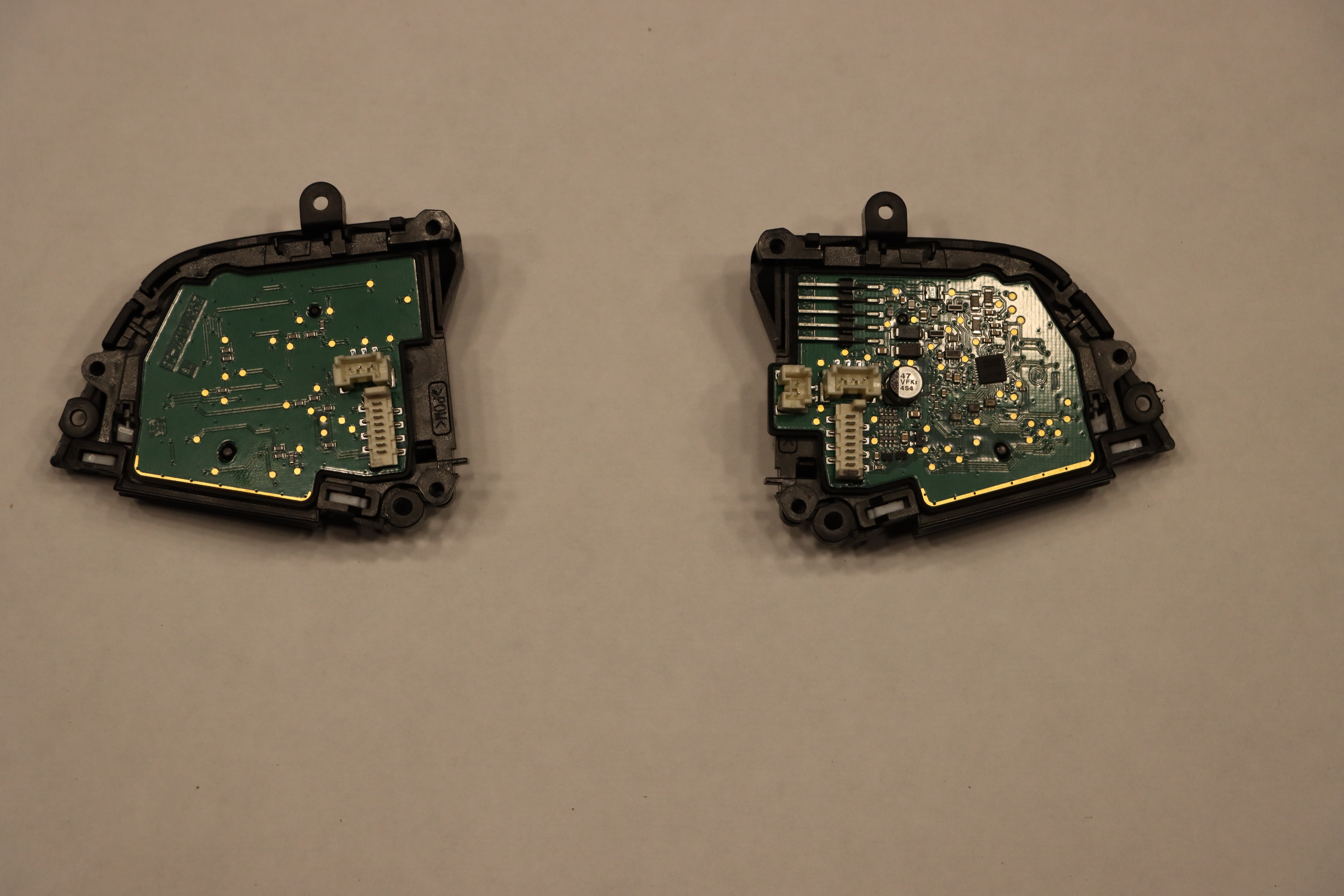 Inside of button assemblies.
Take out the original electronics and replace them by the custom ones. The three wires visible in the images below are for development and will not be on your electronics. Do not touch the contact points on the PCBs and the rubber inlay, contamination might make them malfunction.
 Don't touch the contact points.
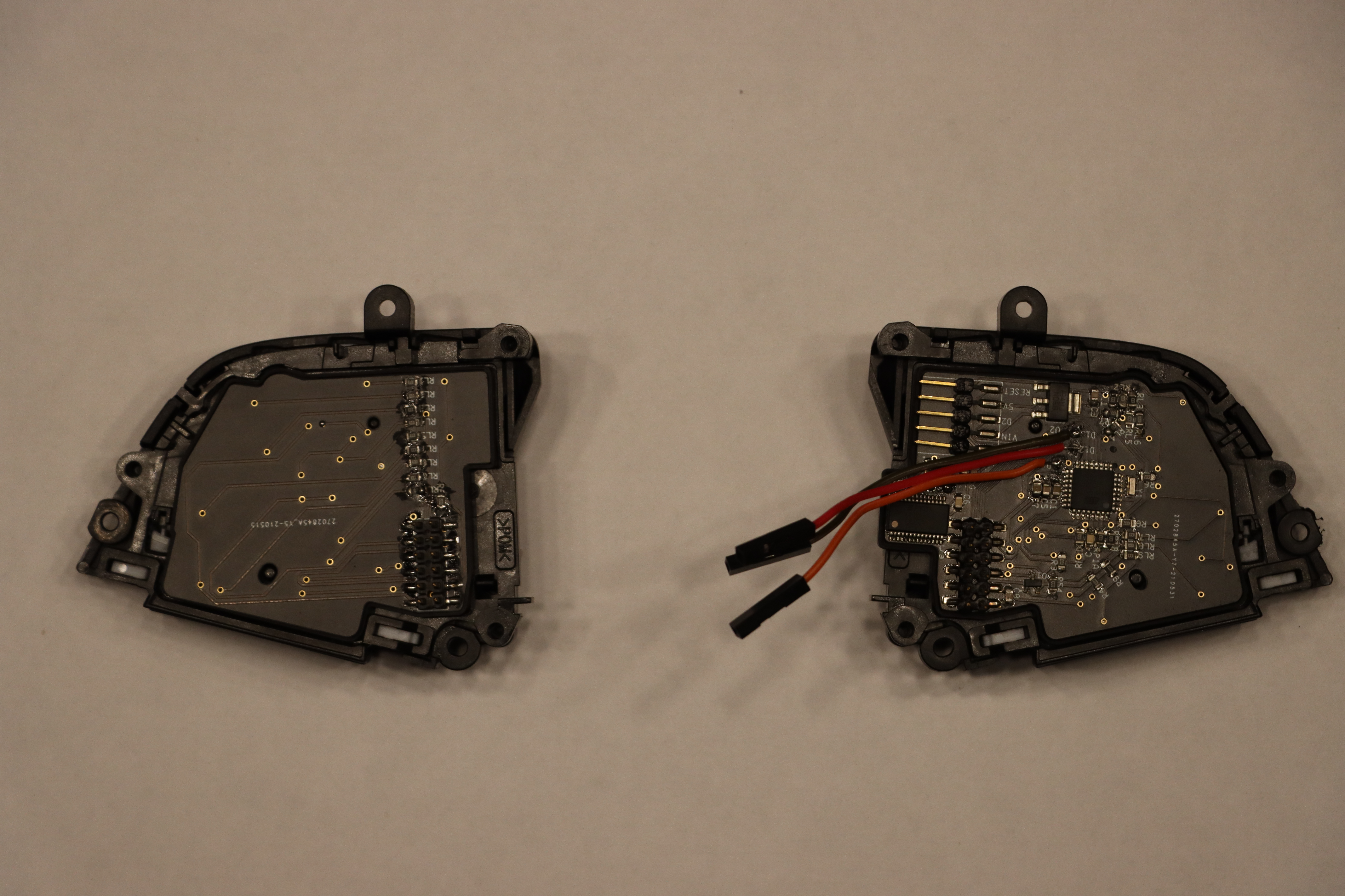 Custom PCBs installed
To be able to connect the new ribbon cable you will need to cut away a small part of the original housing. Make sure that the cable is not in the way when when closing the housing. Carefully fold the ribbon cable between the middle wires and route it to the side as shown below.
 Ribbon cable cutout
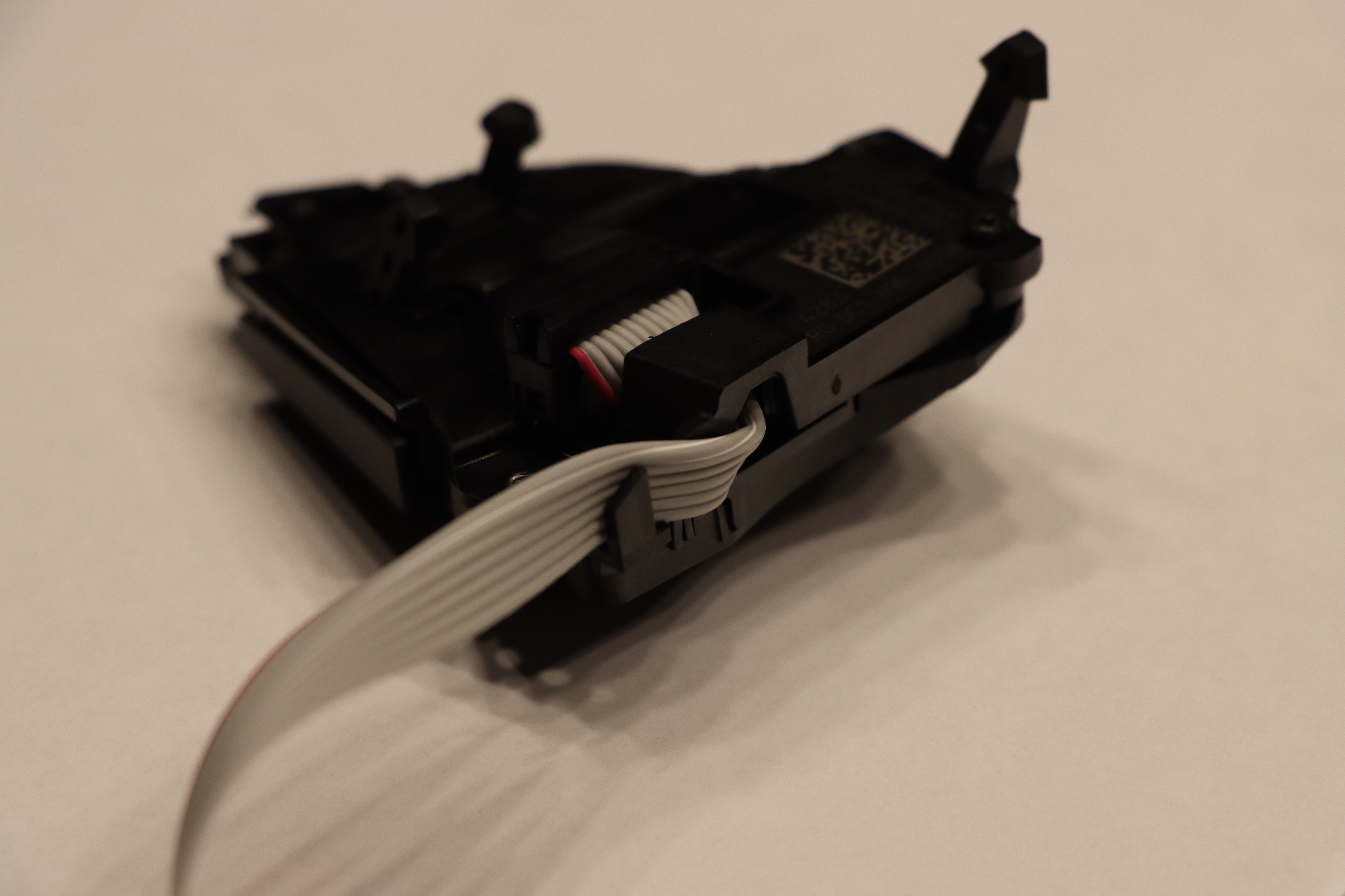 Ribbon cable exit routing
Reinstall the buttons and route the ribbon cable as shown below. Make sure the ribbon will not get jammed when reinstalling the trim on the steering wheel.
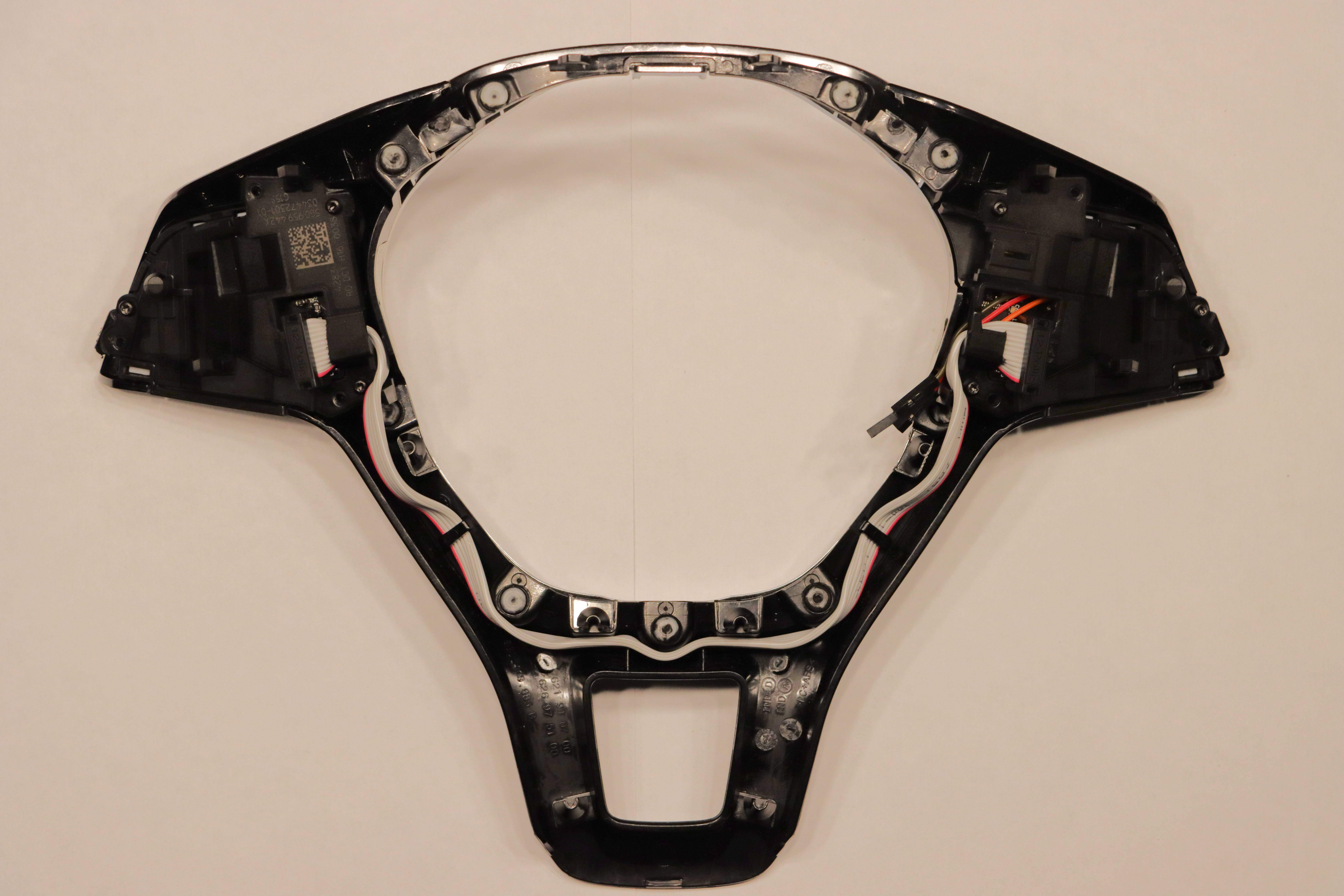 Ribbon cable routing overview
MFSW control module
Parts List
- Arduino Nano
- 2x 10 kOhm resistor
- 2x 220 Ohm resistor
- 1x 4.7 kOhm resistor
- 1x 2-Pin connector of choice*
- 1x 4-Pin connector of choice*
These parts are required for each 12V output (Optional)
- 2N3904 NPN Transistor
- 2N3906 PNP Transistor
- 1x 10 kOhm resistor
- 1x 560 ohm resistor
- 1 Additional pin on a connector of choice
Diagram
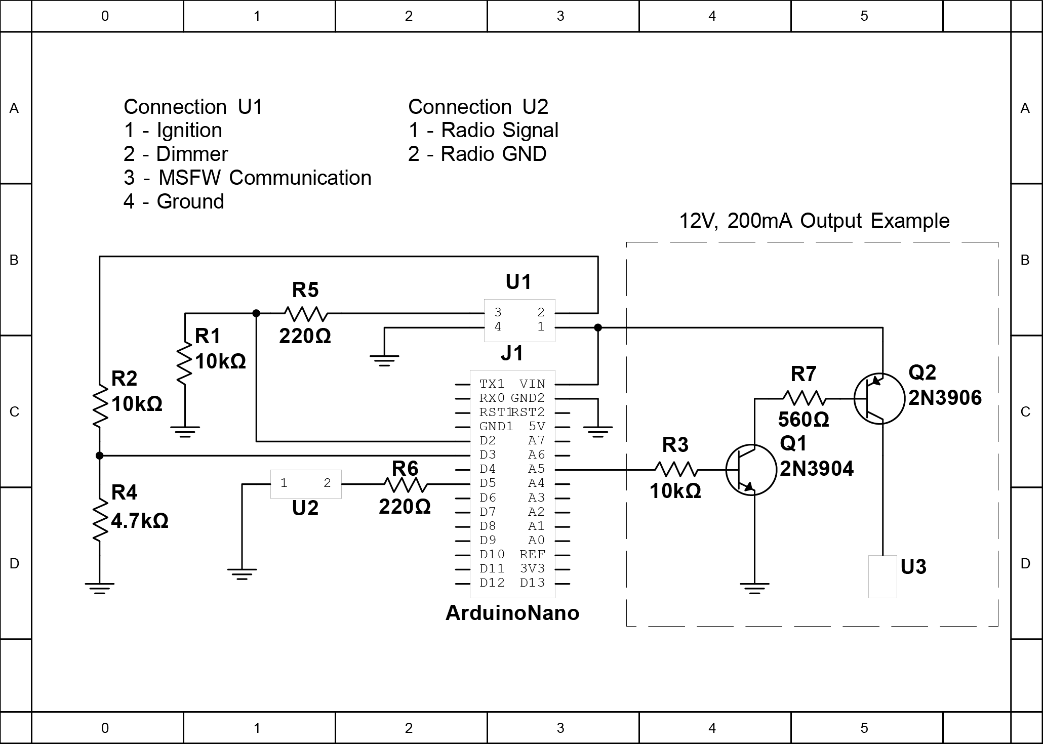 MFSW control module diagram